B Dimension Creation. Free shipping on qualified orders.

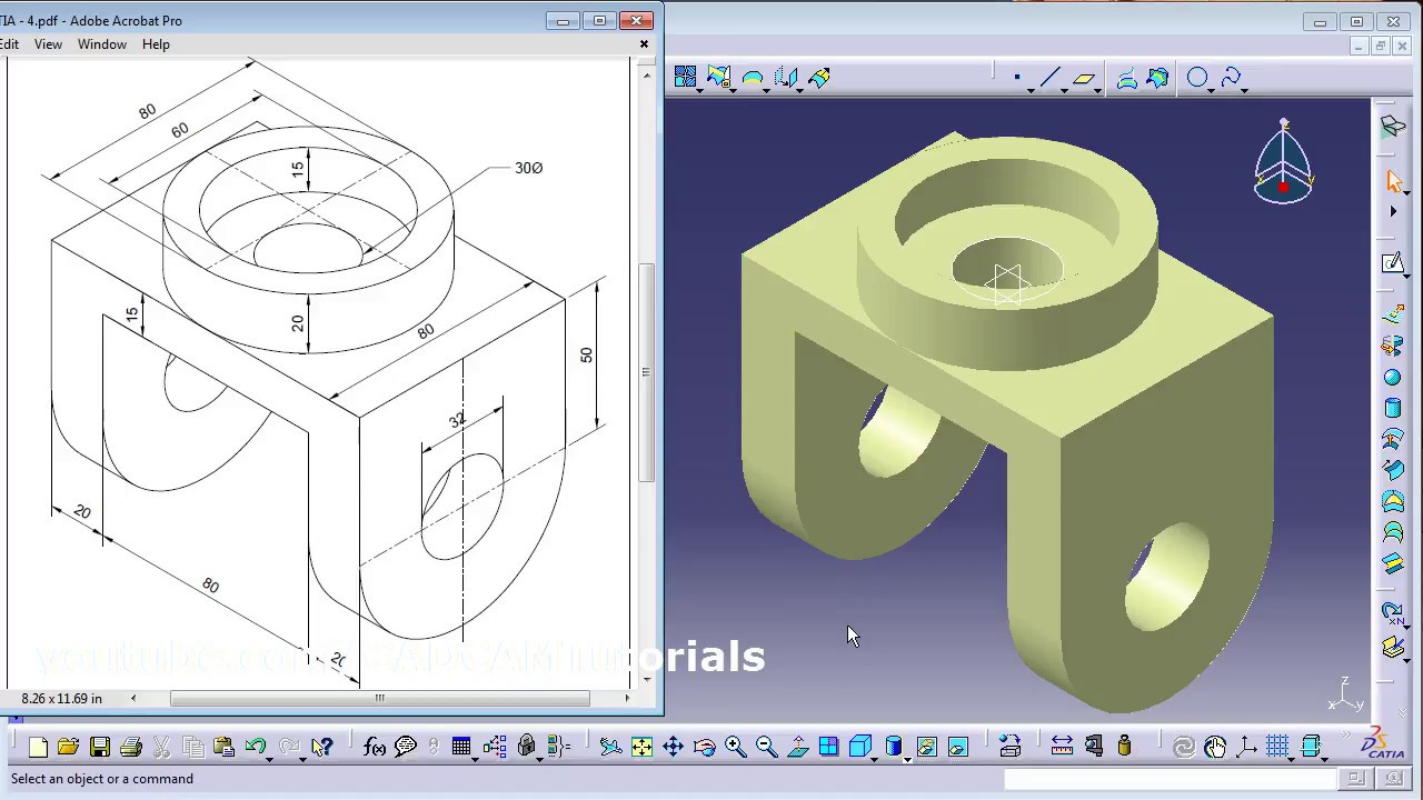
I Need Drawing For Practice In Wireframe And Surface Design Grabcad Questions
Answered on 28 Dec 2019 0242 PM.

. Dimensions for curves 122 Generative Dimensions. Open the catia from the catia icon step 2. Select the Dimension tab in OptionsDimension Creation.
Free easy returns on millions of items. You can select a surface instead and use the surface as your profile. You can turn off the displaying of colors in the drawing if unselecting the icon on the bottom menu in drawing mode.
CATIA V5R16 Fundamentals Constraining the sketch Dimensional Constraints click the icon then select the elements Length Distance Angle RadiusDiameter Remark. You can decide that the dimension line is positioned according to the cursor following it dynamically during the creation process. Dimension does not have 3D element reference.
Thank you for your answer. You can customize given options when creating or re-positioning dimensions. If we need to take this a step further within Tools Options Mechanical Design Drafting Dimension setting By default create dimensions on circles to Edge will take care of this in a more permanent fashion.
In V5R7 dimensions were gray when dimensioning drawing elements generated from mirrored 3D elements. Once you create and dimension the sketch in the part make sure it is shown. This will get rid of snapping.
Select all affected dimensions right click and select Line-Up option. And to do that you have several methods to display that. Which is why when you dimension to an axis in catia the system will give you a number that is double the value.
It thinks you are trying to show a revolved diameter. If u dont have that. Sub CATMain msgbox Select View to Activate Dim InputObject0 InputObject0 DrawingView Dim DrwSelect As Selection Set DrwSelect CATIAActiveDocumentSelection Status DrwSelectSelectElement2InputObject Select View False CATIAStartCommandActivate View DrwSelectClear Dim ZAEHLER As integer Dim Status.
Check if the displayed dimension is 50mm. Eklunja Mechanical 19 Jul 02 0100. CATIA Tutorials Basic Advance and Surfacing tutorials Pdf Download.
There is a square placed on the dimension in the text properties area its not in the tolerance menu. Answered on 7 Feb 2013 0429 AM. CATIA is a French designed Computer Aided Design CAD tool.
When making a drawing in CATIA it is common to add an axis line to features. Right click on tool bar and make sure tha tab is click on. Hope you found todays CATIA Tip in a Minute or Less to be useful if not just interesting.
October 29 2007 1051 PM in response to James Bishop Hello there In 2D drafting when a length dimension is created Right-click will give you an option of curvelinear. 3 View drawings Working Drawings are an important part of the engineering. To reduce the time or you can think of this as a work around you can create a sketch in the part file to represent the mating geometry then show the sketch dimensions in the drawing view without creating a feature for it.
Beside the basic tools of 3D design a number of exercises and examples point to different construction strategies in several applications. Read customer reviews find best sellers. As a rule they show an object from three different views Usually the Front Top Right Side.
On what level you are running CATIA. In that case press and hold shift key while placing. Ananth Narayan 28 Dec 2019 0407 PM.
From drop down option of numerical properties you will get the dimension digit option. CATIA V5R16 surface modeling Mouse Tutorial 2A To confirm that the size of the drawing is correct- Click Dimensions icon. To copy and paste the drawing into 3D space-.
Then CATIA calls to Select a dimension or geometry as reference to line-upin the bottom left corner of the screen. For questions please use the comment form. If not we need to enlarge or shrink the drawing into the correct size.
After you choose the material for you part you can very easy track your dimensions. On the icon is a dimension with a spy glass But beware you will loose the ability to see if the dimension is disconnected from 3D therefore I recommend you to turn it off only before drawing. Generally an axis created anywhere in CATIA tells it to gear up for some type of rotation.
It is similar in use to Autocad NX Formerly known as UG Pro-E. How to display the weight mass center of gravity and surface in CATIA V5. KUNJ THUMMAR 28 Dec 2019 0303 PM.
X 14inThe CATIA V5-6R2015. Upvote 1 Upvoted 2 Downvote 0 Downvoted 1. You will find how to create an angle dimension chamfer dimension length radius diameter and angle with degrees and minutes.
Or go to the main menu Tools Positioning Line-up. ADVANCED SURFACE DESIGN ASCENT Center for Technical Knowledge. Which is why when you dimension to an axis in CATIA the system will give you a number that is double the value.
The dimension will have a curve above the numerical display to indicate what the type is. This tool is used in the design of various objects such as vehicles buildings components etc. Ad Browse discover thousands of brands.
The Line-up dialog box appears. There is a option in catia drafting called numerical properties. There you can change your digit as per desired.
01202017 by Joe Leave a Comment. CATIA to know the design intent. Each of the views are drawn in 2-D two dimensional and have dimensions labeling the length width and height of the object.
Flatness controls how flat a surface must be in order to meet the design requirements. And how to line-up dimensions on the drawing. What is a 3 view drawing.
Click on the scale line of the drawing. Dimension following the mouse ctrl toggles. It is not the purpose of this course to teach GDT but.
If your options are on default dimension colors gray means non assosiative dimensions. Settings dans latelier Drafting. It is a three dimensional modeling tool.
CATIA V5 Drafting Beginner Tutorial How to create a 2D using Drafting. This tutorials includes an introduction of the main features in the 3D design software package Catia V5. Introduction to Surface Design student guide by covering advanced curve and surface topics.
A simple drawing of a CATIA V5 Part. 10m edited 10m. Create a length dimension on a curve.
From your tree select the top element name of the part right click and choose Proprieties. To create the dimensions continuously double-click the icon so that the icon is always on until you re-click it again Geometrical Constraints. Advanced Surface Design student guide expands on the knowledge learned in the CATIA.
Catia Surface Design Exercises For Beginners 2 Catia Surface Design Tutorial Youtube

Catia Simple Surface Design For Beginners Youtube
I Need Drawing For Practice In Wireframe And Surface Design Grabcad Questions

How To Create A Mechanical Part Using Catia Part Design Surface Design Mechanical Design Mechanical Engineering Design
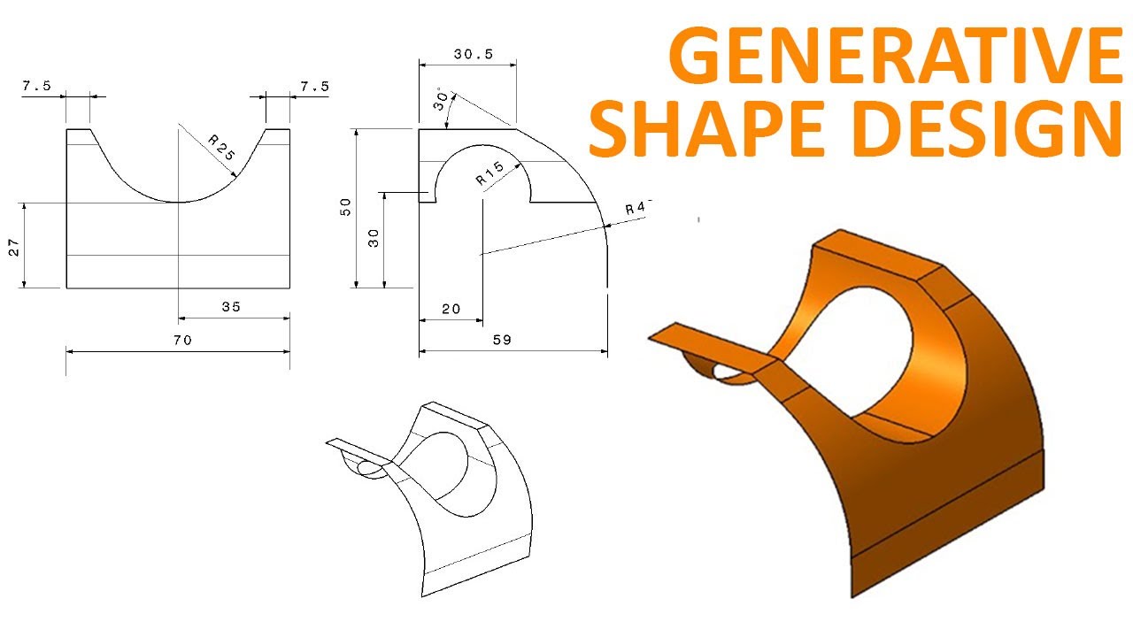
Generative Shape Design 1 Catia V5 Beginner Tutorial How To Use Extrude And Split Youtube

I Need Drawing For Practice In Wireframe And Surface Design Grabcad Questions

I Need Drawing For Practice In Wireframe And Surface Design Grabcad Questions

Pin On Catia V5 Video Tutorials
0 comments
Post a Comment